
Diagrams Of Trailer Electrical Wiring components
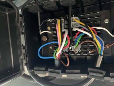
Ifor Williams Junction Box
Wiring Diagrams for 13 pin and 7 pin sockets
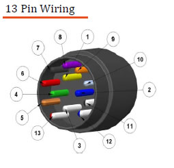
| | Colour | Description |
| 1 | Yellow | LH Indicator |
| 2 | Blue | Rear Fog Lamp |
| 3 | White | Earth for Pins 1 to 8 |
| 4 | Green | RH Indicator |
| 5 | Brown | RH Tail Lamp, End Outline, No Plate Lamp |
| 6 | Red | Stop Lamps |
| 7 | Black | LH Tail Lamp, End Outline, No Plate Lamp |
| 8 | Pink | Reversing Lamp |
| 9 | Orange | 12v Power Feed |
| 10 | Grey | Fridge (IGN Switched Live) |
| 11 | White/Black | Earth for Pin 10 |
| 12 | White/Blue | Spare (Signal) |
| 13 | White/Red | Earth Return for Pin 9 |
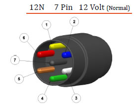
| | Colour | Description |
| 1(L) | Yellow | LH Indicator |
| 2(54G) | Blue | Rear Fog Lamp |
| 3(31) | White | Earth |
| 4(R) | Green | RH Indicator |
| 5(58R) | Brown | RH Tail Lamp, End Outline, No Plate Lamp |
| 6(54) | Red | Stop Lamps |
| 7(58L) | Black | LH Tail Lamp, End Outline, No Plate Lamp |
A 13 pin socket on a trailer with reversing lights will need an adaptor when coupled to a 7 pin socket on a towing vehicle, however the reversing lamp will not be functional.